


 Puttster 2
A couple of years ago I built a simple Warm Air Intake device (WAI Version 1.0)...but it wasn't effective enough in really cold temperatures. I modified it and have done some testing over the last couple of winters. This is a better design...it's simple...and it's easier to build.
Here are the improvements for version 2.0...
- More effective than my original design…results in higher intake air temperatures
- Draws in air from a concentrated heat source (exhaust manifold heat shield)
- Mandrel bends...no internal restrictions...supports more air flow
- Supplements the existing air intake…no need to block existing air cleaner snorkel in most winter conditions
- Can be installed/removed easily without tools
What's new about this design?
This version is designed to specifically draw air in through/around an existing hole in the exhaust manifold heat shield. Here is the area between the engine and firewall. Notice that square hole in the exhaust manifold heat shield right next the oxygen sensor...
Here's a closer look...
This WAI will be positioned so that the intake opening is directly over this hole. This hole in the heat shield isn’t large enough to supply all of the intake air for the car, but the device will not be air-tight against the exhaust manifold heat shield. As a result, it will be drawing in air through the hole in the heat shield along with air from the immediate area around the exhaust manifold. The end result will be warm/hot air entering the rear of the air box.
Here's where the end of the WAI 2.0 will rest on the exhaust manifold...centered over the square hole...
Here's another view...
What you are looking at is a 3"-2" silicone reducer sitting on the exhaust manifold shield (the larger 3" end is on the heat shield). It may look like it is completely sealed against the heat shield, but it's not (it is resting on the shield). So air can enter the WAI through the hole in the manifold heat shield as well as the gaps around the end of the reducer.
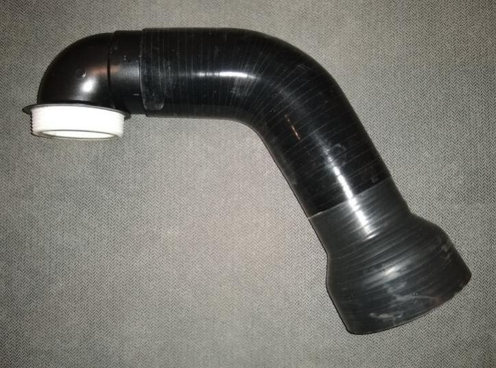
Here's what the WAI 2.0 finished product looks like...

 Reply With Quote